Table of Contents >> Show >> Hide
- What Is Non-Planar Layer FDM?
- Why Non-Planar FDM Matters
- How It Works on Real Printers
- The Real Advantages of Non-Planar Layer FDM
- Why It Is Not Mainstream Yet
- Best Use Cases for Non-Planar FDM
- How to Approach It Without Losing Your Weekend
- The Future of Curved-Layer Printing
- Hands-On Experiences With Non-Planar Layer FDM
- Conclusion
Most FDM printing still behaves like a very obedient pancake chef: one flat layer, then another flat layer, then another, until your model exists and your patience has aged three years. Non-planar layer FDM changes that script. Instead of forcing every toolpath to live on a perfectly horizontal plane, it lets some layers curve, rise, dip, or follow the shape of the part more naturally. The result can be smoother surfaces, fewer ugly stair-steps, better overhang behavior, and in some cases stronger parts. The catch? Your printer, slicer, and sanity all need to cooperate.
That tension is exactly why non-planar 3D printing has fascinated makers, researchers, and slicer developers for years. It feels like the future of FDM, but also like the kind of future that occasionally smacks the nozzle into a half-finished print. Still, the idea is too useful to ignore. Curved-layer printing is no longer just a weird lab demo. It now shows up in hobbyist experiments, open-source slicer workflows, research papers, rotary and multi-axis printer mods, and practical discussions about surface finish, support reduction, and toolpath optimization.
What Is Non-Planar Layer FDM?
Non-planar layer FDM is a form of fused deposition modeling in which the print path is not limited to flat, constant-height layers. In traditional FDM, the nozzle prints a 2D slice, moves up on the Z axis, and prints the next slice. In non-planar FDM, some of those paths are curved or tilted so the nozzle can follow the geometry of the part more closely.
That sounds simple, but it changes a lot. Standard slicing assumes each layer is flat, easy to calculate, and easy to keep collision-free. Once the path becomes curved, the slicer has to think in three dimensions, not two-and-a-half. It must account for nozzle shape, fan shrouds, hotend clearance, extrusion consistency on slopes, and whether the toolhead can physically pass over already-printed geometry without turning the print into modern art.
Not All Non-Planar Printing Looks the Same
There are several flavors of non-planar FDM. One is slightly curved slicing on a normal 3-axis printer, where the top layers or outer shell are gently bent to match shallow domes, curves, or sloped surfaces. Another is hybrid slicing, where the interior remains planar for simplicity, while the visible outer regions use curved toolpaths for better finish. Then there is the spicier version: 4-axis, 5-axis, or 6-axis printing, where a tilted or rotating toolhead can change orientation and print aggressive overhangs or complex surfaces with much more freedom.
So when people say “non-planar printing,” they may mean anything from a few curved skin layers on a desktop printer to a multi-axis machine that looks like it escaped from a robotics lab. Same family, very different dinner guests.
Why Non-Planar FDM Matters
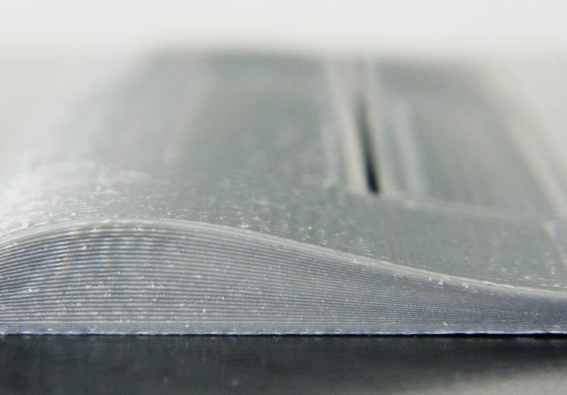
The biggest reason is surface quality. Traditional layer-based printing creates visible stair-stepping on shallow slopes and curved tops. If you print a dome, an airfoil, a helmet shell, or an ergonomic grip with ordinary planar layers, the surface often looks like it was built from tiny geological terraces. Non-planar slicing can reduce that effect by letting the nozzle follow the curve instead of approximating it with many flat steps.
Another reason is support reduction. Overhangs are one of FDM’s oldest enemies. Standard printers can bridge a little and overhang a little, but once the geometry gets too ambitious, gravity enters the chat. Non-planar strategies, especially with tilted or rotary systems, can change the deposition angle so the filament is better supported by previous paths. That can reduce support material, shorten cleanup time, and spare you from chiseling plastic scaffolding off a part like an archaeologist with trust issues.
Mechanical behavior also makes non-planar FDM interesting. Traditional FDM parts are famously anisotropic, meaning they are weaker between layers than within a layer. Non-planar or direction-aware toolpaths can align material more intelligently with surface geometry or expected loads. That does not magically solve every strength problem, but it can improve how forces move through a part, especially in shells, curved features, or specialized designs.
How It Works on Real Printers
On Standard 3-Axis Machines
The most accessible form of non-planar layer FDM happens on ordinary Cartesian or CoreXY printers. In these workflows, the printer still uses X, Y, and Z motion, but the G-code varies the nozzle height continuously during a pass. Usually, this works best for gentle curvature rather than dramatic geometry. Think smoother top surfaces, mildly curved shells, and selective enhancement of visible areas rather than full cinematic freedom.
Many experimental pipelines use a hybrid method: keep the internal volume planar so infill is easy and fast, then add non-planar outer layers near the top or on visible sloped surfaces. This approach is practical because it gives you the benefits where they matter most without forcing the entire print into a computational obstacle course.
On 4-Axis and Multi-Axis Systems
Once you add a tilted nozzle, rotating toolhead, or robotic arm, non-planar printing becomes far more capable. A four-axis setup can let the nozzle approach the part at an angle, which can make extreme overhangs or cylindrical geometries more printable. Five-axis and six-axis systems go even further by changing both position and orientation during deposition.
This is where non-planar FDM starts looking less like a slicer trick and more like a new manufacturing strategy. Complex shells, curved surfaces, airfoils, ducts, props, and geometry that would normally demand supports suddenly become more realistic. Of course, the hardware is more complex, setup is fussier, and the debugging sessions become character-building.
The Real Advantages of Non-Planar Layer FDM
1. Smoother Curved Surfaces
This is the headline benefit. Curved layers can follow the surface of a model instead of approximating it with flat steps. On domes, shallow slopes, sculptural prints, or consumer-facing parts, that can mean better aesthetics right off the printer and less sanding afterward.
2. Better Use of Material Direction
Because filament paths can follow geometry more naturally, non-planar printing can sometimes place material in directions that better resist stress, especially in shells and load-bearing contours. It is not a magic strength button, but it gives designers more control than classic pancake stacking.
3. Reduced Need for Supports
Curved and angled toolpaths can make certain overhangs more printable. In multi-axis systems, this benefit becomes even stronger because the tool orientation can be adjusted dynamically. Less support means less waste, faster finishing, and fewer scars on the final part.
4. More Interesting Design Freedom
Non-planar slicing encourages designers to think beyond “What can be stacked flat?” and toward “What can be laid along the shape?” That opens doors for aerodynamic surfaces, tactile forms, thin curved skins, molds, and functional surfaces where finish actually matters.
Why It Is Not Mainstream Yet
Collision Avoidance Is Brutal
The nozzle is not a mathematical point. It has a body, a heater block, sometimes a sock, fan ducts, mounting hardware, and an attitude. A curved toolpath that looks perfect in theory can fail if any part of the printhead clips the part. This is one of the biggest reasons non-planar slicing is still hard to integrate cleanly into mass-market slicers.
Extrusion Gets Tricky
When the nozzle moves across changing slopes, the relationship between layer height, line width, contact area, and flow becomes more complicated. You are not just printing a line; you are printing a line on a moving height field. That means tuning becomes more sensitive, especially if the printer is not mechanically stiff or the Z axis cannot respond quickly and smoothly.
Mainstream Slicer Support Is Still Incomplete
Despite years of interest, non-planar printing is still mostly living in research projects, issue trackers, post-processors, experimental forks, and niche pipelines rather than polished default menus in mainstream slicing software. That tells you something important: the concept is valuable, but the implementation burden is real.
Some Parts Simply Do Not Benefit Much
If your part is boxy, mostly vertical, or destined for filler primer and sandpaper anyway, non-planar FDM may be overkill. It shines most on visible curves, shallow slopes, support-heavy shapes, and geometry where orientation and surface conformity matter. On a simple bracket, it can be the 3D-printing equivalent of bringing a violin quartet to a sandwich order.
Best Use Cases for Non-Planar FDM
Non-planar layer FDM makes the most sense when the geometry and the payoff match the extra complexity. Good candidates include airfoils, fan blades, ducts, decorative shells, cosplay surfaces, curved lids, ergonomic handles, thin-walled forms, and prototypes where the top surface finish matters. It is also promising for research applications involving continuous-fiber composites, robotic deposition, and large-format printing on non-flat substrates.
For makers, the sweet spot is often hybrid non-planar printing on standard printers. You keep the easy reliability of planar infill and use curved outer layers only where they noticeably improve the part. That is the practical middle ground between “boring but dependable” and “my printer now identifies as a six-axis art installation.”
How to Approach It Without Losing Your Weekend
Start Small
Begin with a part that has a gentle curved top surface. Do not start with a turbine blade, a helmet, and a dream. A small dome, ergonomic cap, or simple sloped housing will teach you more with fewer tears.
Respect Clearance
Nozzle shape, fan shroud height, probe placement, and hotend bulk all matter. Even if the G-code looks valid, your hardware may disagree. Conservative curvature and generous safety margins are your friends.
Use Hybrid Strategies
Hybrid slicing is one of the smartest ways to use non-planar FDM today. Print the core with ordinary planar layers, then switch to non-planar shell or skin regions where finish improvements justify the effort.
Expect Slower Iteration
This is not a plug-and-play feature on most printers. Toolpath generation may take longer, setup can be fussier, and failures can be more mysterious than standard FDM problems. That does not make it bad. It just means you should treat it like an advanced workflow, not a weekend checkbox.
The Future of Curved-Layer Printing
The direction of travel is clear: better algorithms, more automated hybrid slicing, stronger collision modeling, improved post-processors, and closer links between geometry, stress analysis, and toolpath planning. Research is increasingly treating non-planar additive manufacturing as a full system problem involving software, hardware, process control, and part performance rather than a one-off gimmick for pretty tops.
That matters because non-planar printing is not only about aesthetics. It is part of a broader shift toward smarter material placement in additive manufacturing. Instead of asking the printer to build every shape with flat layers because that is convenient for software, engineers are asking the software to respect the shape and function of the part. That is a much better question.
Hands-On Experiences With Non-Planar Layer FDM
In practical maker workflows, experiences with non-planar layer FDM usually begin with optimism and end with a new respect for nozzle geometry. The first successful print is often a small curved cap or decorative top shell, and when it works, the result feels almost unfair. The stair-stepping that looked inevitable in a standard slice suddenly softens, and the top surface comes off the bed looking closer to a finished object than a prototype begging for sandpaper.
Then comes the second print, which is where non-planar printing starts acting like a proper teacher. Maybe the curvature is a little too aggressive. Maybe the fan duct clips the part. Maybe the printer handles slow, smooth Z movement well in one region and gets twitchy in another. A lot of users discover that non-planar success has less to do with bravery and more to do with restraint. Small curves, controlled amplitudes, modest speeds, and realistic geometry tend to win.
Another common experience is realizing that non-planar FDM changes how you judge “good enough” in design. A part that looked ordinary in CAD becomes much more interesting when you know the toolpath can follow the surface. Suddenly, shallow domes, blended transitions, ergonomic grips, and soft contours feel more worth modeling because the printer can reward that effort. You stop designing purely for flat stacking and start designing for surface flow.
There is also a very specific kind of satisfaction in hybrid workflows. Many hobbyists and researchers report that the most practical setup is not full non-planar everything, but planar guts with a curved outer shell. That approach feels sensible in use. You get most of the reliability of classic FDM for the bulk of the part, while the visible surfaces benefit from the smoother finish of non-planar motion. It is a little like wearing work boots with a tailored jacket: practical underneath, stylish where people actually look.
Failures, however, are spectacularly educational. A standard failed print often gives you spaghetti. A non-planar failed print can give you something that looks like your printer attempted abstract sculpture while emotionally processing geometry. When the nozzle drags across a previously printed ridge, it becomes obvious that collision avoidance is not an academic footnote. It is the whole game. That lesson tends to make users more attentive to hotend shape, probe placement, and the seemingly boring details that ordinary slicing often lets you ignore.
One of the more encouraging experiences around non-planar printing is that it often makes people better at standard printing too. After working through curved toolpaths, you become far more aware of extrusion behavior, line support, flow consistency, path order, and motion planning. Even if you return to ordinary planar slicing, you do so with sharper instincts. You notice where surface quality is really coming from, where support waste is unnecessary, and where part orientation could do more of the heavy lifting.
Perhaps the most honest real-world takeaway is this: non-planar layer FDM is exciting not because it is already effortless, but because it makes desktop printing feel open again. It reminds users that FDM is not a finished box with one correct method. It is still a living process, full of strange ideas, clever hacks, academic breakthroughs, and workshop experiments that occasionally become tomorrow’s standard feature. That spirit is a big part of the appeal. Non-planar printing may not replace traditional slicing any time soon, but it absolutely expands what FDM can be.
Conclusion
Non-planar layer FDM is one of the most compelling directions in material extrusion 3D printing because it attacks several long-standing weaknesses of standard FDM at once. It can improve curved surface finish, reduce visible layer stepping, cut down support use in the right geometry, and create smarter toolpaths that better respect the shape of a part. At the same time, it remains demanding. Collision avoidance, incomplete slicer support, hardware limits, and tuning complexity keep it from becoming a one-click feature for the average desktop user.
That does not make it niche in a bad way. It makes it important. Non-planar slicing shows where FDM is headed: away from rigid flat-layer assumptions and toward geometry-aware, function-aware printing. For makers, designers, and engineers willing to experiment, it offers a glimpse of a more capable future. For everyone else, it is still worth watching, because the moment mainstream slicers make it easier, a whole lot of layer lines are going to have a very bad day.