Table of Contents >> Show >> Hide
- What Is a PCB Motor?
- Why Put the Motor Inside the Robot’s Circuit Board?
- How Tiny PCB Motors Actually Work
- Key Design Challenges
- Where PCB Motors Make the Most Sense
- Design Steps for a Tiny Robot PCB Motor
- Advantages of Designing Motors Into the PCB
- Limitations You Should Not Ignore
- Real-World Inspiration: Micro Robots and PCB Actuators
- Practical Experience: Lessons From Designing Tiny Motors Into Robot Circuit Boards
- Conclusion
There is something wonderfully sneaky about a robot whose motor is not bolted on, snapped in, or zip-tied to the frame like an afterthought. Instead, the motor is part of the circuit board itself. The same printed circuit board that carries power, sensors, chips, and signals can also create motion. That is the idea behind designing tiny motors right into the robot’s circuit board, and it feels a little like discovering that your kitchen table can also make espresso.
In traditional robot design, the motor is usually a separate component. Engineers select a small DC motor, servo, stepper, or brushless motor, then design the robot around it. That works well, but it also adds bulk, weight, wiring, connectors, mounting hardware, alignment problems, and cost. For micro robots, swarms, compact drones, medical devices, tiny actuators, and experimental machines, every millimeter matters. A separate motor may be the biggest part of the whole robot, which is awkward when the goal is “make it smaller,” not “build a motor with a robot attached.”
PCB motors flip that thinking around. Instead of winding copper wire around a metal stator, the motor coils are formed from copper traces printed directly on a circuit board. Add permanent magnets, a rotor, bearings, a motor driver, and control logic, and the board becomes both the electrical brain and part of the mechanical muscle. It is not magic, but it is clever enough to make a robot builder grin like they just found extra fries at the bottom of the bag.
What Is a PCB Motor?
A PCB motor is an electric motor that uses a printed circuit board as part of its electromagnetic structure. In many designs, the board acts as the stator, the stationary part of the motor. Copper traces are shaped into spiral coils or other winding patterns. When current flows through those traces in the right sequence, the coils create magnetic fields. Those fields interact with magnets in the rotor, causing the rotor to spin.
The most common approach for very thin PCB motors is the axial-flux layout. In an axial-flux motor, the magnetic flux travels along the axis of rotation, and the rotor usually looks like a small disk facing the flat PCB stator. This geometry makes sense for circuit boards because PCBs are already flat. Instead of forcing a round motor can onto a flat robot, the designer uses the board’s natural shape as part of the motor.
A tiny PCB motor can include several major elements: copper coil traces, vias connecting layers, a rotor with small permanent magnets, a bearing or shaft support, a brushless DC motor driver, power regulation, and firmware for commutation. The design can be sensorless, using back electromotive force to estimate rotor position, or it can use Hall sensors or other feedback methods when precise control is needed.
Why Put the Motor Inside the Robot’s Circuit Board?
The first reason is size. Robots are always fighting a three-way battle between space, weight, and power. A circuit-board motor removes separate windings, housings, brackets, and long wire runs. For small robots, that can mean the difference between a working prototype and a charming pile of parts that almost fits together.
The second reason is integration. When the motor, driver, power electronics, and control signals live close together, the design can become cleaner. Fewer connectors mean fewer failure points. Shorter current paths can reduce wiring mess. Manufacturing can also become more repeatable because the stator geometry is defined by PCB fabrication instead of hand-wound coils.
The third reason is scalability. PCB manufacturing is already mature, precise, and widely available. Once a coil pattern is designed, it can be reproduced many times with consistent dimensions. That matters for swarm robotics, low-cost educational robots, small consumer devices, and research platforms where making one robot is interesting, but making fifty identical robots is the real test.
How Tiny PCB Motors Actually Work
The PCB Becomes the Stator
In a conventional brushless DC motor, the stator is made from wire windings, often wrapped around iron teeth. In a PCB motor, the windings are etched as copper traces. These traces may appear as flat spirals arranged in phases. A three-phase brushless design, for example, energizes different coil groups in sequence so the magnetic field appears to rotate. The rotor follows that rotating field, producing motion.
Using PCB traces instead of round wire offers precision, but it also creates limits. Copper traces are thin compared with wound copper wire. That can restrict current capacity and increase resistance. More resistance means more heat. More heat means the board starts asking uncomfortable questions like, “Did you really need full throttle for this long?”
The Rotor Carries the Magnets
The rotor is usually the mechanical part that still needs careful assembly. It may contain tiny permanent magnets arranged with alternating poles. These magnets must be aligned properly to interact with the PCB coils. In very small motors, the rotor may be a lightweight disk, a small ring, or a shaftless bearing-supported part. Precision matters because a tiny wobble can become a big problem when the rotor spins at very high speed.
The Driver Controls the Dance
A PCB motor does not spin just because copper traces look pretty. It needs a motor driver to switch current through the phases at the right time. For a brushless DC motor, that usually means a compact driver IC, MOSFETs or integrated switching stages, PWM speed control, and firmware that handles startup and commutation. Sensorless control can reduce component count, while sensor-based control can improve low-speed behavior and positioning.
Key Design Challenges
Torque Is the Big Boss Fight
The hardest part of making a useful PCB motor is generating enough torque. Tiny flat coils do not automatically produce the same magnetic strength as traditional wound stators. The designer has to optimize trace width, copper thickness, number of turns, number of layers, coil shape, magnet strength, air gap, and current level. Every choice affects the others.
A small air gap between the rotor magnets and PCB coils improves magnetic coupling, but it also increases mechanical sensitivity. More copper layers can increase the number of turns, but they raise cost and may complicate heat flow. Wider traces reduce resistance but leave less room for turns. Narrower traces allow more turns but heat up faster. PCB motor design is basically a tiny negotiation between physics, manufacturing, and your budget.
Heat Management Is Not Optional
Heat is one of the biggest enemies of integrated motors. Because the coils are built into the circuit board, the board must handle electrical current and thermal stress. If the copper traces run too hot, performance drops, materials age faster, and nearby electronics may suffer. Thermal vias, larger copper pours, careful duty-cycle limits, thicker copper, and smart firmware can all help.
Designers also need to think about where the heat goes. A motor integrated into a tiny robot may not have a fan, a metal chassis, or much airflow. The PCB itself may become the heat spreader. That means layout is not just about routing signals; it is also about giving heat an escape route.
Motor Noise Can Attack the Electronics
Motors are electrically noisy. Fast switching, current spikes, and magnetic fields can interfere with sensors, radios, microcontrollers, and analog circuits. In a PCB-integrated motor, the noisy part and the sensitive part may be neighbors. That is convenient for packaging and slightly rude for signal integrity.
Good layout practices are essential. High-current motor paths should be kept away from sensitive sensor traces. Grounding needs to be planned carefully. Decoupling capacitors should sit close to driver ICs. Power planes, return paths, trace width, and EMI control must be considered early, not sprinkled on at the end like decorative parsley.
Where PCB Motors Make the Most Sense
PCB motors are not a universal replacement for every motor. They shine when the robot needs compact motion, low profile, reduced assembly complexity, or highly integrated electronics. They are especially appealing for micro robots, tiny wheeled bots, miniature fans, small pumps, optical mechanisms, lightweight drones, educational kits, art robots, haptic devices, and experimental actuators.
They can also be useful when the motor does not need huge torque but does need precise, repeatable, compact motion. A tiny robot that rolls across a desk, flaps a lightweight wing, turns a miniature sensor, or spins a small wheel may benefit more from integration than from raw power.
For larger applications, PCB stator technology can scale beyond hobby projects. Companies working on axial-flux PCB stator motors are exploring designs for robotics, HVAC systems, pumps, e-mobility, aerospace, and precision motion. The common theme is not “make every motor a PCB motor.” The smarter idea is “design the motor around the system instead of forcing the system around a catalog motor.”
Design Steps for a Tiny Robot PCB Motor
1. Define the Motion Requirement
Before drawing a single coil, define what the motor must do. Does the robot need speed, torque, positioning, quiet motion, or short bursts of movement? A motor for a tiny fan is different from a motor for a wheel. A wheel may need stronger startup torque and better low-speed control. A fan may tolerate high speed with lower torque. A flapping mechanism may care more about weight and response than continuous rotation.
2. Choose the Motor Architecture
For very thin robots, an axial-flux brushless design is often the obvious candidate. The PCB can hold the stator coils, while the rotor disk sits above it. For some designs, a linear actuator or flexible PCB coil may make more sense than a rotating motor. The architecture should follow the robot’s job, not the other way around.
3. Design the Coil Geometry
Coil geometry affects torque, resistance, heat, and manufacturability. Designers must decide how many coils to use, how many turns each coil should have, how wide the copper traces should be, and how many PCB layers are worth paying for. A two-layer board may be cheap but weak. A six-layer board may improve performance but increase cost. The best answer depends on the robot’s size, current limits, and production goals.
4. Select Magnets and Rotor Hardware
The magnets must match the coil layout. Stronger magnets can improve torque, but they may increase cost, assembly difficulty, and attraction forces. The rotor needs stable support, especially at high speed. Bearings, friction, balance, and air gap control all matter. In tiny motors, mechanical design can be just as important as electrical design.
5. Plan the Driver and Firmware
The motor driver must fit the current, voltage, and control method. Some modern driver chips can handle sensorless BLDC control in a very small package, which is great for tiny robots. Firmware should include safe startup behavior, current limits, speed control, stall handling, and thermal protection. A tiny motor that works only until it overheats is not a motor; it is a dramatic countdown timer.
6. Prototype, Measure, Repeat
PCB motors are perfect candidates for iterative design. Build one version, measure speed, torque, current draw, temperature, vibration, and startup reliability. Then adjust the coil pattern, copper weight, magnet spacing, driver settings, or rotor design. The board may look simple, but performance usually improves through several rounds of testing.
Advantages of Designing Motors Into the PCB
The most obvious advantage is compactness. A PCB motor can reduce the total height and footprint of a robot. This makes it easier to create thin, lightweight machines that still move. Integration can also reduce assembly steps because the stator is manufactured with the electronics rather than installed as a separate part.
Another advantage is consistency. PCB manufacturing can reproduce trace patterns accurately, which helps when multiple robots must behave the same way. The design can also combine motor coils, driver electronics, sensors, connectors, and control logic on one board. For product development, this can simplify supply chains and reduce mechanical complexity.
There is also creative freedom. Once designers stop treating motors as separate cans, they can explore new robot shapes. Motors can be built into wheels, hinges, flaps, compact modules, or distributed actuation systems. A circuit board can become a structure, a nervous system, and a motion platform all at once.
Limitations You Should Not Ignore
PCB motors are exciting, but they are not miracle pancakes. They often produce less torque than conventional motors of similar diameter, especially when limited by thin copper and heat. They may require more careful rotor assembly. They can be sensitive to air gap, board warping, and manufacturing tolerances. They also demand strong electrical design because motor currents and control electronics share the same limited space.
For robots that need high torque, heavy loads, rugged industrial duty, or long continuous operation, a traditional motor may still be the better choice. PCB motors are most compelling when integration, thinness, precision, and manufacturability outweigh the need for brute force.
Real-World Inspiration: Micro Robots and PCB Actuators
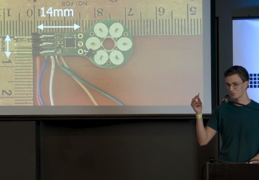
One of the most famous examples in the maker and robotics world comes from experiments with ultra-thin PCB motors and microbot electronics. These projects show how a motor can be reduced to a small board, a rotor, magnets, and clever control electronics. Some designs have demonstrated extremely high rotational speeds in a package small enough to fit into miniature robots and compact modules.
The larger lesson is not just that tiny motors can spin fast. The lesson is that electromechanical design is becoming more integrated. Instead of designing electronics first and mechanics second, or mechanics first and electronics second, engineers are blending both from the beginning. The PCB is no longer just a place to put components. It can become part of the machine’s physical behavior.
Practical Experience: Lessons From Designing Tiny Motors Into Robot Circuit Boards
Working with PCB-integrated motors teaches a designer humility very quickly. On paper, the concept looks clean: draw coils, add magnets, connect a driver, spin the rotor. In reality, every tiny detail has a vote. The copper thickness votes. The magnet spacing votes. The bearing friction votes. The firmware votes twice and then asks for a firmware update.
One of the first lessons is to prototype the motor as a test platform before committing it to the final robot. It is tempting to make one beautiful all-in-one board that includes the microcontroller, sensors, battery charger, wireless module, motor coils, and mechanical mounting holes. That board will look impressive, but debugging it can be painful. A better approach is to create a small motor test PCB first. Use it to evaluate coil geometry, rotor spacing, startup behavior, current draw, and heat. Once the motor works reliably, integrate it into the full robot board.
Another practical lesson is that the air gap is everything. A motor may perform well when the rotor sits close to the coils, then lose torque dramatically when the gap increases by a small amount. This means mechanical tolerances must be designed into the board from the start. Mounting holes, spacers, bearing seats, rotor retainers, and board flatness all matter. If the robot frame flexes, the motor performance may change. If the rotor rubs, the robot becomes a very small smoke machine with ambition.
Thermal testing should begin early. Touch testing is not enough, and neither is wishful thinking. Measure board temperature during startup, steady operation, and repeated bursts. If the robot will run from a small lithium battery, test the motor at real battery voltages, including lower-voltage conditions near discharge. Motors often behave differently when the supply sags. The driver may reset, the microcontroller may brown out, or the motor may fail to start under load.
Power routing deserves serious attention. A tiny robot board can contain both delicate logic and pulsing motor currents. Keep high-current loops compact. Place decoupling capacitors close to the driver. Give the motor current a clean return path. Avoid routing sensitive analog sensor traces beside motor phase traces. If the robot has a radio module, test wireless performance while the motor is running, not only while the robot is politely sitting still.
Firmware also makes or breaks the design. A tiny PCB motor may need a controlled startup sequence because sensorless motors can struggle at very low speed. Current limits, soft start, stall detection, and speed ramping can make the difference between a smooth robot and a twitchy desk ornament. Logging current and speed during tests is extremely useful. Even basic data can reveal whether a problem is mechanical friction, insufficient torque, poor commutation, or voltage drop.
The final lesson is to design for assembly. Tiny magnets are powerful, slippery, and surprisingly talented at jumping onto tools. Rotor assembly needs a repeatable process. Mark magnet polarity clearly. Use jigs where possible. Plan how the bearing, rotor, and board will be aligned. A PCB motor that only works when assembled by one patient engineer under perfect lighting is not ready for production. It may, however, be ready to become a dramatic lab story.
Designing tiny motors directly into a robot’s circuit board is not the easiest path, but it is one of the most interesting. It forces the designer to think like an electrical engineer, mechanical engineer, firmware developer, and manufacturing planner at the same time. The reward is a robot that feels less assembled and more grown from a single idea: a board that does not just think, but moves.
Conclusion
Designing tiny motors right into the robot’s circuit board is a powerful example of modern electromechanical integration. By using PCB traces as motor coils, engineers can create ultra-compact actuators that reduce parts, save space, simplify assembly, and open new possibilities for micro robots and lightweight machines. The approach is especially promising for small robots where every gram, wire, and screw matters.
Still, PCB motors require careful design. Torque, heat, EMI, rotor alignment, driver selection, and firmware control all need attention. These motors are not a replacement for every conventional motor, but when used in the right application, they can make a robot smaller, smarter, cleaner, and more elegant. In a world where robots are shrinking and expectations are growing, the humble circuit board may become one of the most exciting places to hide a motor in plain sight.