Table of Contents >> Show >> Hide
- What Is the MH-CD42 Charger Board (and Why Do Makers Love It)?
- MH-CD42 vs TP4056: Why People Upgrade
- Pinout Tour: The Pads You Actually Touch
- What’s Inside: The “Power Bank Brain” in Plain English
- Choosing the Right Battery (So You Don’t Turn “DIY” Into “Why Is It Smoking?”)
- Wiring It Up: A Clean, Safe, “Don’t Make It Weird” Setup
- Quick Bench Tests (That Teach You More Than Guessing)
- The Auto Shutoff Quirk: “Why Did My Project Randomly Turn Off?”
- Project Ideas That Pair Well With the MH-CD42 Module
- When You Should Not Use an MH-CD42 Charger Board
- Troubleshooting: Fast Fixes Before You Desolder Everything
- Conclusion: The MH-CD42 Is a Tiny ShortcutWith Opinions
- Hands-On Experiences: What You’ll Learn the First Weekend (500+ Words of Realistic Maker Lessons)
The MH-CD42 charger board is one of those tiny modules that shows up in your parts bin, stares at you with four little LEDs,
and quietly whispers, “I can turn this random 18650 into a pocket-sized power plant.” It’s a charge controller, a boost converter,
a protection circuit, and a battery gaugepacked onto a board about the size of a postage stamp. Which is equal parts convenient
and mildly suspicious (because whenever something looks this simple, it’s definitely hiding at least one quirky behavior).
In this guide, we’ll poke, prod, and generally play around with the MH-CD42 module: what it does, how it compares to the
classic TP4056 setup, how to wire it safely, what to expect under load, and why your ultra-low-power project might make it
dramatically “rage quit” after 30 seconds. Along the way, we’ll keep it practical, a little nerdy, and just humorous enough to
keep your soldering iron from feeling judged.
What Is the MH-CD42 Charger Board (and Why Do Makers Love It)?
At a high level, the MH-CD42 is a 1-cell lithium battery power management board. You feed it 5V (typically from USB), it charges
a single Li-ion/LiPo cell up to the standard 4.2V full-charge level, and it can boost the battery back up to a regulated 5V output
for your project. In other words: it behaves like the “brains” of a DIY power bank.
Typical features you get in one little board
- Charging input: 5V-ish in (often labeled VIN), usually happy in the ~4.5V–5.5V neighborhood.
- Single-cell charging: for 1S lithium cells (3.7V nominal, 4.2V full).
- Boost output: 5V output for USB-powered devices and microcontroller projects.
- Battery protection: over-charge, over-discharge, over-current, and short-circuit protection (implementation varies by board version).
- LED fuel gauge: four LEDs that estimate remaining charge like a tiny, judgmental gas gauge.
The main keyword here is MH-CD42 charger board, but you’ll also see it sold as a “charge/discharge module,” “power bank board,”
or “IP5306-based 5V boost charger module.” Different listings, same vibe: “Make battery-powered stuff easier.”
MH-CD42 vs TP4056: Why People Upgrade
The TP4056 module is the old reliable of DIY lithium charging: cheap, common, and perfectly fine at charging a single cell.
But it’s also kind of a “bring-your-own-everything-else” situation.
What TP4056 boards usually require
- A separate boost converter if you need 5V output
- Often a separate protection board (unless you bought a TP4056+protection variant)
- Extra wiring and extra chances to do something… exciting… like reverse polarity
What MH-CD42 bundles together
- Charging + protection + 5V boost output on one PCB
- Higher advertised charge/output currents than the most common TP4056 breakout setups
- Battery level LEDs built in
If you’re building a portable projectESP32 sensor node, Raspberry Pi Pico gadget, LED art piece, or a tiny “why not” power bankthe MH-CD42
is appealing because it removes a lot of the glue work. Fewer modules. Fewer interconnects. Fewer “Why does this wire look toasted?” moments.
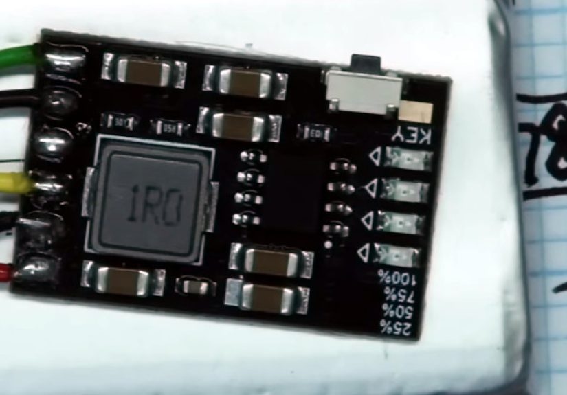
Pinout Tour: The Pads You Actually Touch
Most MH-CD42 boards expose solder pads for input, battery, and output. Some include a USB connector for charging input, while others expect you
to solder VIN and GND directly. The labeling can vary a little, but the function is consistent.
Common MH-CD42 pin labels
- VIN: 5V input for charging
- GND: ground (shared reference for everything)
- BAT: battery positive (connect to the + of your 1S cell)
- OUT-5V (or VOUT): boosted 5V output positive
- KEY: button/trigger input for enabling output or checking battery level (implementation varies)
Practical tip: treat the ground pads like they’re all the same node (because they usually are), but still wire them neatly.
Messy ground wiring is how you accidentally invent a noise generator.
What’s Inside: The “Power Bank Brain” in Plain English
Many MH-CD42 boards are associated with the IP5306 (or a close functional equivalent). That family of chips was designed for portable
chargers and power banksexactly the job you’re trying to make it do.
Charging behavior: CC/CV, because lithium batteries have boundaries
Lithium charging is typically a two-stage process: constant current until the battery approaches the target voltage, then
constant voltage while the current tapers down. That taper is the charger politely asking the battery, “Are you full yet?”
until the battery says, “Stop. I’m full. I’m going to sit down now.”
Why it matters: if your project is powered while charging, the board is juggling two jobs at oncecharging the cell and feeding your load.
Depending on your power source and load, the charger may reduce charging current, warm up, or behave differently than when it’s charging a battery
alone on the bench.
Boost conversion: from ~3.0–4.2V up to 5V
A single Li-ion cell isn’t 5V. It’s roughly 4.2V full, slides through the 3s during normal use, and eventually hits the “please stop”
region near 3.0V. The MH-CD42 boosts that varying battery voltage to a steady 5V output using a switching converter (the inductor on the board is
a dead giveaway).
You’ll often see optimistic efficiency claims (because marketing loves hope), but in practice, efficiency depends on load current, battery voltage,
and component quality. Translation: it’s usually fine, but don’t expect miracles at the edge of its rated output.
Protection features: the guardrails (not a guarantee)
Many MH-CD42 boards include protection functions such as over-current and short-circuit shutdown, plus over-charge and over-discharge protection
for the battery. This is a big step up from “raw battery directly to project,” but it’s not a free pass to ignore battery safety. You still need
sane wiring, decent cells, and a healthy respect for the fact that lithium batteries store enough energy to turn mistakes into heat.
Choosing the Right Battery (So You Don’t Turn “DIY” Into “Why Is It Smoking?”)
One reason the MH-CD42 is both awesome and dangerous is that it can ask a lot from a battery. Many boards advertise charge currents up to
around 2A. That’s fine for some cellsand totally inappropriate for others.
18650 vs LiPo pouch cells
- 18650 cells (good quality, genuine) often tolerate higher charge/discharge currents, especially in the 2500–3500mAh range.
- Small LiPo pouches (like 500–1000mAh) may have lower recommended charge rates. Forcing ~2A into a small pouch is a bad plan.
Rule of thumb: match charge current to the battery’s spec. If you don’t know the spec, assume it’s lower than your optimism and higher than your fear
and then pick something conservative anyway. If your board doesn’t let you set charge current, you “set” it by choosing an appropriate battery and
not using the module outside its comfort zone.
Parallel cells are okay (series cells are not)
The MH-CD42 is for 1S packs. If you want more capacity, you can use multiple cells in parallel (with proper matching and precautions),
but do not use it for series packs. If you need 2S/3S charging and protection, you need a different BMS and charger design.
Wiring It Up: A Clean, Safe, “Don’t Make It Weird” Setup
Step 1: Connect the battery
Connect your battery’s positive terminal to BAT and the negative to GND. Double-check polarity. Then check it again.
Polarity mistakes are the fastest way to discover whether your board includes reverse protection (spoiler: assume it doesn’t).
Step 2: Connect your load
Connect your device’s positive input to OUT-5V and the device ground to GND. Use wire appropriate to your current.
If you’re pulling anywhere near an amp, thin jumper wires are a performance art piece, not engineering.
Step 3: Connect charging input
Apply 5V to VIN and ground to GND. If your board has a USB port, this is “plug in cable, feel superior.”
If not, it’s “solder wires, feel brave.”
Pro tip: you may need a stronger 5V supply than you think
If you charge the battery and power a device at the same time, your input source may need to deliver the combined current.
A weak USB port can cause brownouts, slow charging, flickering LEDs, or the board behaving like it’s offended.
Quick Bench Tests (That Teach You More Than Guessing)
You don’t need a lab-grade setup to understand your MH-CD42 module. A multimeter and a cheap USB load tester can reveal most of what you need to know.
Test A: Does it charge correctly?
- Start with a partially discharged battery (not dead-flat).
- Apply 5V input.
- Measure battery voltage rising toward 4.2V over time.
- Feel the board carefully: warm is normal; hot is a problem.
Test B: Can it hold 5V under load?
- Connect a known load (USB dummy load, resistor bank, or a device you don’t cry over).
- Measure output voltage at OUT-5V and GND.
- Increase load and watch for voltage sag or shutdown.
Test C: Battery life math (the fun kind of math)
Example: a 3000mAh 18650 is roughly 3.0Ah × 3.7V ≈ 11.1Wh. If your device draws 500mA at 5V, that’s 2.5W.
Ignoring losses, 11.1Wh / 2.5W ≈ 4.4 hours. Now subtract boost losses and real-world battery behavior and you’ll land closer to 3.5–4 hours.
That’s still pretty good for something you built in your kitchen.
The Auto Shutoff Quirk: “Why Did My Project Randomly Turn Off?”
Here’s the biggest “gotcha” with many MH-CD42 boards: they’re designed like power banks. Power banks assume that if current draw is tiny for a while,
the user is done, and they shut off to save power. That’s great for charging a phone; it’s less great for a sensor node sipping 20mA.
What it looks like
- Your project boots, runs, and then shuts off after a short time.
- The LEDs go dark.
- You start blaming your code, your wiring, the moon, and possibly your childhood.
What to do about it
- Add a small “keep-alive” load: a resistor or LED that draws enough current to stay above the cutoff threshold (trade-off: wasted power).
- Pulse a load periodically: some designs “tickle” the KEY/enable behavior or draw short bursts of current to keep it awake.
- Choose the right variant: some board versions or similar modules are designed for always-on output (better for low-power electronics).
- Use a different power architecture: if you truly need microamp sleep currents, a power-bank IC may not be the right tool.
This is not a flaw so much as a personality trait. You didn’t buy a quiet librarian. You bought a bouncer. If the party gets too calm, it kicks everyone out.
Project Ideas That Pair Well With the MH-CD42 Module
1) Portable microcontroller builds
ESP32, Arduino-class boards, Raspberry Pi Picoanything that wants 5V input and doesn’t spend its life below ultra-low-power thresholds.
Great for handheld gadgets, test rigs, and “I swear it’s a prototype” devices.
2) DIY power bank for a single device
If you want a simple power bank board that isn’t a full custom PCB effort, MH-CD42 is the shortcut. Add a decent cell, a case, and a switch,
and you’ve got a charger + booster in one.
3) LEDs and small displays
Addressable LEDs (with sane current limits), small TFTs, or low-power lighting projects work nicelyespecially because the board already has a
button-like behavior (KEY) that can double as your “check battery” control.
When You Should Not Use an MH-CD42 Charger Board
- Multi-cell series packs: this is a 1S solution.
- Tiny LiPo pouches with low charge ratings: charging too fast is unsafe and shortens battery life.
- Always-on ultra-low-power devices: auto-shutdown behavior can be a deal-breaker.
- Loads above the board’s comfort zone: “2.1A” on a listing doesn’t mean “2.1A forever in a sealed box at 95°F.”
- Safety-critical products: hobby modules are for hobby work unless you can fully validate behavior and protections.
Troubleshooting: Fast Fixes Before You Desolder Everything
No 5V output
- Verify battery voltage isn’t below cutoff (many boards protect around ~3V-ish).
- Check for output auto-shutdown due to light load.
- Inspect for solder bridgesespecially between OUT-5V and GND (aka “instant sadness”).
Battery not charging
- Confirm you actually have 5V at VIN under load (weak USB cables are professional liars).
- Check polarity at BAT/GND.
- Try charging with the load disconnected to rule out power-path weirdness.
Board gets hot
- Reduce load current or improve airflow.
- Use a higher capacity cell (lower internal resistance can help).
- Stop using mystery batteries from the “definitely authentic” drawer.
Conclusion: The MH-CD42 Is a Tiny ShortcutWith Opinions
The MH-CD42 charger board is a surprisingly capable all-in-one module for DIY battery-powered projects: it charges a 1S lithium battery from a 5V input,
boosts that battery to a usable 5V output, and adds helpful protections plus a simple LED fuel gauge. If your project draws a reasonable load and you’re
using an appropriate battery, it’s a clean way to get “power bank behavior” without designing a PCB from scratch.
Just remember the big trade-off: many MH-CD42 boards behave like real power banks, including an auto shutoff at light loads. If you plan for thateither by
choosing the right variant, adding a keep-alive strategy, or selecting a different power solution when neededyou’ll have a module that feels like a cheat code
for portable electronics.
Hands-On Experiences: What You’ll Learn the First Weekend (500+ Words of Realistic Maker Lessons)
The first time you “play around” with an MH-CD42 module, you’ll probably have an instant confidence spikebecause it’s so small and straightforward that your
brain assumes it must be foolproof. Then, about 12 minutes later, you’ll learn that “straightforward” and “predictable” are not synonyms in the land of tiny
power boards.
Experience #1: USB cables are the secret final boss. You plug the board in, the LEDs do a cute little glow, and you assume you’re charging at
heroic current. Then you put a meter on VIN and discover your “5V” source is more like “4.6V and emotionally unavailable,” because the cable is thin, long,
and possibly made of recycled spaghetti. Swap to a better cable and suddenly everything improves. It’s not glamorous, but it’s real.
Experience #2: You’ll meet voltage sag and it will not introduce itself politely. Under no load, OUT-5V looks perfect. Under a real loadsay a
microcontroller plus LEDs or a small speaker ampyou might see the output dip a bit during peaks. That’s not the board being “bad,” it’s the battery and
converter doing math in real time. If the battery is low, sag is more likely. If the wires are thin, sag is more likely. If your load is spiky, sag is more
likely. You’ll come away with a new appreciation for short, thick wires and decent cells.
Experience #3: The auto-shutoff moment is a rite of passage. You build a low-power sensor node. It boots. It logs data. You feel like an
unstoppable genius. Then it turns off, seemingly out of spite. This is where you learn the MH-CD42 isn’t designed for “sip power forever” projects by default.
It wants to see enough current draw to believe it’s doing something useful. Your next move might be adding a tiny keep-alive load, or programming the device
to wake up and draw a burst of current periodically, or choosing a different always-on regulator/charger architecture. Either way, you just gained a real-world
power design lesson that no “perfect schematic” ever teaches.
Experience #4: You’ll start treating batteries like components, not “magic cans.” Swap a high-quality 18650 for a worn-out one and the
behavior changesless heat, better runtime, steadier output. Use a small pouch cell and you’ll become cautious about charge current. Try a mystery cell and
you’ll discover why datasheets exist. The MH-CD42 makes these differences obvious quickly, which is actually a gift: it trains you to respect battery specs.
Experience #5: You’ll get better at designing around limitations. Maybe you add a small buck regulator after the 5V output to get a clean 3.3V
rail for sensors. Maybe you add an on/off switch and decide whether you want the MH-CD42 always connected or only connected when needed. Maybe you put it in a
case and suddenly realize physical design matters because exposed pads are basically “short circuit invitations.” The board pushes you into thinking about the
whole system: electrical, thermal, and mechanical.
By the end of that first weekend, you’ll have a working battery-powered prototypeand you’ll also have a short list of “things I will do differently next time.”
That’s the point. The MH-CD42 isn’t just a module; it’s a tiny training ground for power management, battery safety, and practical electronics designserved with
four LEDs and a little bit of attitude.