Table of Contents >> Show >> Hide
- What Is a UNIX Clock?
- The Basic UNIX Clock Design
- Mistake One: Designing the PCB Before Choosing the Displays
- Mistake Two: Assuming Every LED Display Runs Happily at 5 Volts
- Driving Ten Seven-Segment Displays
- Mistake Three: Treating the Enclosure as an Easy Final Step
- Keeping Time With a Battery-Backed RTC
- Mistake Four: Writing a Complicated I2C Library Without Needing One
- Setting the Clock With Two Buttons
- Mistake Five: Avoiding a Main PCB to Save Time
- Mistake Six: Testing on a PC and Forgetting the Microcontroller Is Different
- A More Reliable Build Process
- What the Finished UNIX Clock Teaches
- Hands-On Experiences From Building a UNIX Clock
A UNIX clock sounds like the perfect weekend electronics project. Take the current UNIX timestamp, send it to a row of seven-segment displays, and watch the number increase once per second. No calendar graphics, no animated weather icons, and no alarm tone designed to ruin a perfectly good morning. How difficult could it be?
As many makers eventually discover, the phrase “How difficult could it be?” is often the official opening ceremony for several weeks of debugging. A seemingly simple UNIX clock can involve incompatible display footprints, unexpected voltage requirements, inaccurate assumptions about real-time clock modules, troublesome enclosure fabrication, excessive wiring, and software bugs caused by the difference between desktop computers and small microcontrollers.
That is precisely what makes this type of project valuable. The finished clock is interesting, but the mistakes made while building it teach far more about PCB design, embedded programming, power management, timekeeping, and hardware troubleshooting.
What Is a UNIX Clock?
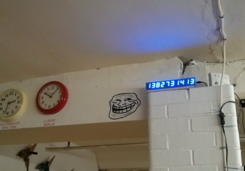
UNIX time represents a moment as the number of seconds that have passed since 00:00:00 UTC on January 1, 1970. That starting point is commonly called the UNIX epoch. Instead of displaying a familiar date such as July 24, 2026, a UNIX clock displays a steadily increasing integer.
To a person unfamiliar with software, the clock may look like a malfunctioning gas-station price sign. To programmers, database administrators, and system engineers, it is instantly recognizable. UNIX timestamps are widely used in operating systems, databases, application logs, file systems, web services, and programming languages because numbers are relatively easy to store, compare, sort, and transmit.
Why Build a Physical UNIX Timestamp Display?
A conventional digital clock answers a practical question: “What time is it?” A UNIX timestamp clock answers a more entertaining question: “How many seconds have escaped since 1970?”
It is also an excellent embedded electronics project because it combines several important skills:
- Reading a real-time clock over an I2C connection
- Converting calendar values into a UNIX timestamp
- Driving multiple seven-segment LED displays
- Managing different voltage rails
- Designing custom printed circuit boards
- Debouncing physical buttons
- Building and testing an enclosure
- Debugging integer-size and data-conversion problems
In other words, it is a clock disguised as an entire introductory embedded-systems course.
The Basic UNIX Clock Design
A practical version of the project can be built around an Arduino Pro Mini or another ATmega328P-based controller. The microcontroller does not need enormous processing power. Its main responsibilities are reading the time, calculating or storing the timestamp, updating the display, and responding to buttons.
A typical hardware plan includes:
- An Arduino Pro Mini or comparable microcontroller board
- A battery-backed real-time clock module
- Ten seven-segment displays
- LED drivers or shift registers
- Two buttons for setting the clock
- A regulated power supply
- A custom display PCB or several linked display boards
- An acrylic, wood, or 3D-printed enclosure
Ten digits are useful because contemporary UNIX timestamps contain ten decimal digits. The display itself could theoretically continue showing ten-digit values until the timestamp exceeds 9,999,999,999. However, the actual operating range also depends on the integer type used by the firmware.
Mistake One: Designing the PCB Before Choosing the Displays
One of the most expensive beginner PCB mistakes is assuming that components with similar descriptions have identical physical dimensions. Two products may both be sold as one-inch, common-anode, seven-segment displays while having different pin spacing, package widths, internal wiring, forward voltages, or pin assignments.
Designing the footprint before purchasing or fully specifying the display can result in a beautiful PCB that fits absolutely nothing. It becomes a technologically advanced drink coaster.
Why Display Footprints Vary
The advertised display size normally describes the approximate digit height, not the exact body dimensions or pin pitch. Manufacturers may arrange the common pins differently, reverse segment connections, change the number of internal LEDs per segment, or use a package that is slightly wider than a competing model.
Even a small spacing error matters. Through-hole leads can tolerate limited bending, but forcing them into incorrect holes risks cracked packages, damaged pads, stressed solder joints, and unpleasant conversations with a pair of pliers.
A Better PCB Workflow
Select the exact display part before routing the board. Download the manufacturer’s datasheet and verify the mechanical drawing, pin numbering, polarity, recommended current, and forward voltage. Then print the PCB layout at actual size and physically place the component over the paper footprint.
This one-to-one paper check takes minutes and can prevent another fabrication order. Also inspect the footprint from the correct viewing direction. A pinout viewed from the bottom is not the same as a pinout viewed from the front, a fact that has introduced many makers to the exciting world of mirrored wiring.
Mistake Two: Assuming Every LED Display Runs Happily at 5 Volts
Standard red seven-segment displays are relatively forgiving because red LEDs often have a lower forward voltage. Large blue displays can be more demanding. A segment may contain multiple LEDs in series, producing a total forward-voltage requirement that approaches or exceeds a 5-volt supply.
If the selected displays need a higher anode voltage while the controller and LED driver require 5 volts, the project suddenly needs two power rails. This may require a boost converter, an additional regulator, cut traces, jumper wires, or a redesigned board.
Plan the Power Architecture First
Before fabricating anything, create a power budget. Record the required voltage and maximum current for every major part. Pay special attention to the number of segments that may be illuminated simultaneously.
A ten-digit timestamp can light dozens of LED segments at once. Even with constant-current drivers, the supply must provide sufficient current without excessive voltage drop or overheating. Include local decoupling capacitors near integrated circuits, use appropriately sized traces, and leave room for test points.
Where uncertainty exists, add configuration options. Solder jumpers, zero-ohm resistors, separate LED-power inputs, and optional regulator footprints are inexpensive insurance. A tiny jumper designed into the board is much more elegant than performing PCB surgery under a desk lamp at 2:00 a.m.
Driving Ten Seven-Segment Displays
Multiple displays are commonly controlled through multiplexing. In a multiplexed design, only one digit or group of digits is activated at a time. The controller switches between them quickly enough that human vision perceives a continuous display.
Multiplexing reduces component count and can lower average power consumption. However, it requires reliable refresh timing. If the microcontroller becomes busy, brightness may become uneven or the digits may flicker.
Using a Driver on Each Display Board
Another approach is to place a constant-current LED driver or shift-register driver on every digit module. Data can be shifted through a chain, latched, and displayed without constantly scanning each digit.
This modular design uses more components but simplifies expansion. Each board can contain one seven-segment display, one driver, and connectors or solder pads for power, clock, data, latch, and output-enable signals. Additional digits are added by connecting another identical module.
Constant-current drivers also help produce consistent brightness without relying solely on individual resistor tolerances. Still, designers must confirm whether the driver supports common-anode or common-cathode displays and whether its outputs can tolerate the selected LED supply voltage.
Mistake Three: Treating the Enclosure as an Easy Final Step
Electronics projects have a mysterious ability to work perfectly while spread across a workbench and fail immediately after being placed inside a box. Enclosures introduce alignment errors, cable strain, blocked connectors, trapped heat, inaccessible buttons, and openings that are approximately correct in the same way a parking space is approximately a garage.
A transparent acrylic case is especially attractive for a UNIX clock because the circuit boards and wiring become part of the visual design. Finger-jointed panels can be created with vector-design software and cut on a laser cutter.
Test the Laser Before Cutting the Entire Case
Laser power, focus, material thickness, surface flatness, and cutting speed all affect whether the beam passes completely through the acrylic. Cutting performance can also vary across the machine’s working area if the bed or optics are misaligned.
Run small test cuts near the center and edges before committing to the full enclosure. Check the kerf, joint fit, corner quality, and whether protective film should remain in place during cutting. If the laser does not cut through, removing half-detached shapes by hand can become a long and delicate exercise involving a knife, patience, and several new vocabulary words.
Keeping Time With a Battery-Backed RTC
A microcontroller can count seconds using its internal oscillator, but it is not an ideal long-term clock. Oscillator frequency changes with temperature, supply voltage, component tolerance, and age. Small errors accumulate into noticeable drift.
A dedicated real-time clock, such as a DS3231-based module, is a better solution. The DS3231 contains an integrated temperature-compensated crystal oscillator and communicates through I2C. A backup battery allows it to continue tracking the date and time while the main project is unplugged.
The controller can read calendar fields from the RTC, convert them into a UNIX timestamp, and send the decimal digits to the display. Alternatively, it can read the RTC periodically and increment a local timestamp between checks.
RTC Time Is Not Automatically UNIX Time
Many real-time clocks store seconds, minutes, hours, day, month, and year in separate registers. Some use binary-coded decimal rather than ordinary binary integers. Firmware must read those fields correctly and convert them into seconds since the UNIX epoch.
That conversion must account for month lengths, leap years, and the fact that century years are leap years only when divisible by 400. Time-zone conversion should usually be avoided inside the clock. UNIX timestamps are normally based on UTC, so the simplest design stores and displays UTC-based time.
Mistake Four: Writing a Complicated I2C Library Without Needing One
Building low-level software can be educational. It can also consume most of the project schedule while delivering a feature that a mature library already provides.
An interrupt-driven I2C state machine may be appropriate for a system that must perform several time-sensitive tasks concurrently. A clock that updates once per second usually does not need that complexity. A straightforward blocking I2C transaction is unlikely to create a visible delay.
The important lesson is not that custom libraries are bad. Writing one can teach valuable details about bus states, acknowledgments, interrupts, and error recovery. The lesson is to understand the trade-off. Use established libraries when the primary objective is finishing the clock. Write the low-level driver when learning I2C is itself part of the objective.
A basic logic analyzer is extremely useful in either case. It can reveal missing acknowledgments, incorrect addresses, malformed start conditions, timing problems, and buses held low. Hardware debugging tools often cost less than the hours spent guessing why a register refuses to answer.
Setting the Clock With Two Buttons
A battery-backed RTC should rarely need manual adjustment, but buttons remain useful during development, battery replacement, initial setup, or recovery from corrupted data.
A compact interface can use one button to select a digit and another to increment it. Holding the increment button can accelerate the change rate. The firmware should debounce both inputs because mechanical switches do not produce one clean transition. Their contacts bounce rapidly, which can otherwise make one press appear to be several.
While the user is editing the timestamp, the normal display update should pause or operate through a clearly defined state machine. Once editing is complete, the firmware validates the value, converts it back into calendar fields if necessary, and writes the corrected time to the RTC.
Mistake Five: Avoiding a Main PCB to Save Time
Connecting several ready-made modules with individual wires initially seems faster than designing another circuit board. Sometimes it is. However, a project containing a controller board, RTC module, power converter, display chain, USB connector, and buttons can quickly become a dense web of point-to-point wiring.
Every connection is another potential fault. Wires can break, connectors can loosen, and mislabeled conductors can turn troubleshooting into electrical archaeology.
A simple carrier PCB can reduce assembly time and improve reliability. It does not need to replace every module. It can merely provide mounting holes, power distribution, connectors, labeled test points, and organized signal routing. Spending an evening designing that board may save several evenings of soldering and repair.
Mistake Six: Testing on a PC and Forgetting the Microcontroller Is Different
Time-conversion code may work perfectly on a desktop computer and fail on an 8-bit microcontroller because C and C++ integer sizes are not identical across every platform.
On many AVR systems, an int is 16 bits. On common desktop systems, it is usually 32 bits. An intermediate calculation that silently uses a 16-bit integer can truncate a perfectly valid 32-bit UNIX timestamp.
Use explicit fixed-width types such as uint32_t or uint64_t, and make sure constants and intermediate expressions are promoted to a sufficiently wide type. Compiler warnings should be enabled and treated seriously. A warning about conversion or overflow is often the compiler politely explaining tomorrow’s bug.
The Year 2038 and the Year 2106
A signed 32-bit UNIX timestamp reaches its maximum value on January 19, 2038. Modern 64-bit systems largely avoid this limitation, but older embedded devices and legacy interfaces may still be affected.
An unsigned 32-bit counter extends the positive range to February 7, 2106, although it cannot represent dates before 1970. A ten-digit display has an even larger decimal range, but the firmware will never reach it unless the timestamp is stored in a wider integer.
For a new build, using a 64-bit timestamp is generally sensible. The additional storage cost is tiny for most modern microcontrollers, and the clock will be prepared for a future in which its acrylic enclosure has probably become a museum exhibit.
A More Reliable Build Process
The following sequence prevents many of the mistakes that turn a quick UNIX clock into an accidental research program:
- Choose the exact displays and download their datasheet.
- Prototype one digit with the intended LED driver.
- Measure segment current and verify brightness.
- Calculate the full system’s current requirements.
- Prototype the RTC and time-conversion code separately.
- Test timestamps around leap days and integer boundaries.
- Print PCB footprints at actual size before fabrication.
- Add configuration jumpers and accessible test points.
- Build and test one display module before ordering many copies.
- Make a cardboard enclosure prototype before laser cutting acrylic.
- Test the completed electronics outside the final enclosure.
- Document voltages, connectors, pin assignments, and firmware versions.
The objective is not to eliminate every mistake. That would remove much of the traditional character from electronics. The objective is to make mistakes cheaply, early, and one at a time.
What the Finished UNIX Clock Teaches
The completed clock is more than a row of glowing numbers. It demonstrates the relationship between software time and physical timekeeping, while exposing the practical realities hidden beneath a simple block diagram.
Component dimensions matter. LED colors affect voltage requirements. Enclosures deserve prototypes. Software libraries involve trade-offs. Data types are part of hardware design. Test equipment can be a better investment than replacement components. Most importantly, the word “simple” should never be used near an unfinished electronics project where the project can hear it.
Mistakes do not make the build unsuccessful. When documented and understood, they become the most reusable part of the project.
Hands-On Experiences From Building a UNIX Clock
The first stage of a UNIX clock build often feels wonderfully productive. One display is connected on a breadboard, a test program sends a few digits, and everything lights up. The maker sees “1234” and immediately imagines ten perfect blue digits glowing inside a transparent case. At this point, confidence is high and the number of undiscovered problems is even higher.
The experience changes when the complete display chain is assembled. A segment that looked bright during a one-digit test may appear dim when many outputs are active. Long wires introduce voltage drops and intermittent connections. One display may be rotated or wired differently, transforming an eight into something resembling a folding chair. Labeling every connection suddenly stops feeling overly cautious.
PCB arrival day produces another emotional journey. Opening a package of professionally manufactured boards feels like receiving equipment from a miniature space program. Then the first display is placed over the footprint and the pins do not line up. The board is still beautiful, purple, and completely confident in its wrongness.
This is where practical habits develop. The builder checks the datasheet again, measures the actual component, compares the footprint, and discovers whether the problem came from package selection, viewing direction, or a simple unit-conversion error. The next board revision includes clearer labels, larger pads, test points, mounting holes, and perhaps several slightly paranoid configuration jumpers.
Firmware testing creates a different kind of confusion. The RTC may report a reasonable date while the display shows an absurd timestamp. Logging each intermediate value helps isolate whether the error occurs while reading binary-coded decimal, calculating leap years, multiplying days by 86,400, or converting between integer types.
Boundary tests are especially revealing. Useful test dates include the UNIX epoch, the final day of February during leap and non-leap years, the transition into a new year, the maximum supported timestamp, and values that exceed 16-bit arithmetic. A clock that works only on today’s date is not fully tested; it is merely feeling cooperative.
Enclosure assembly brings another lesson: serviceability matters. A case should allow access to programming headers, buttons, screws, and replaceable batteries. Permanently gluing the final panel before the last firmware upload is a memorable mistake that usually happens only once.
The most satisfying moment arrives when the clock is unplugged, left without power, and connected again later. The RTC has continued counting, the controller starts correctly, and the ten-digit display resumes as though nothing happened. After hours of tracing wires and questioning arithmetic, a number increasing once per second feels surprisingly dramatic.
The broader experience is one of learning to replace assumptions with measurements. Do not assume the footprint fits; print it. Do not assume the voltage is sufficient; measure it. Do not assume a variable is 32 bits; check the compiler and type definition. Do not assume the laser cut through; test the corner before pulling the sheet from the bed.
A UNIX clock therefore becomes a compact record of engineering judgment. Every corrected trace, jumper wire, firmware patch, and revised panel represents a lesson that improves the next project. The clock counts seconds, but the builder learns to count assumptions.