
Table of Contents >> Show >> Hide
- Can You Import a PDF Directly Into SOLIDWORKS?
- PDF to SOLIDWORKS: The Best Workflow at a Glance
- Method 1: Convert a Vector PDF to DXF or DWG, Then Import It Into SOLIDWORKS
- Method 2: Import the Converted File as a SOLIDWORKS Drawing
- Method 3: Import the Converted File as a Sketch for 3D Modeling
- Method 4: Use a Scanned PDF as a Sketch Picture
- Method 5: Use Autotrace for Simple Shapes and Logos
- Method 6: Use PDF-to-CAD Conversion Software
- Common Problems When Converting PDF to SOLIDWORKS
- Best Practices for a Clean PDF to SOLIDWORKS Conversion
- Example: Converting a PDF Bracket Drawing Into a SOLIDWORKS Part
- When You Should Remodel Instead of Convert
- Experience Notes: What Actually Works in Real PDF-to-SOLIDWORKS Projects
- Conclusion
So, you have a PDF drawing and you want it inside SOLIDWORKS. Easy, right? Just click “Convert PDF to 3D magic,” grab coffee, and return to a perfect part file? Sadly, no. SOLIDWORKS is powerful, but it is not a mind-reading machine that can instantly turn a flat PDF into a fully parametric model with clean sketches, design intent, mates, features, and a tiny engineer inside saying, “I dimensioned this for you.”
The good news is that you absolutely can convert a PDF file to SOLIDWORKS-friendly geometry for drawings, sketches, reference layouts, and even 3D modeling. The trick is understanding what kind of PDF you have and choosing the right workflow. A vector PDF can often be converted to DXF or DWG, then imported into SOLIDWORKS as editable 2D geometry. A scanned PDF, on the other hand, is basically a photograph wearing a business suit. It may need tracing, vectorization, or manual remodeling.
This guide explains how to convert PDF to SOLIDWORKS for drawings and more, including the best methods for PDF to DXF, PDF to DWG, scanned drawings, image tracing, scaling, cleanup, and turning imported geometry into usable parts. Let’s rescue that PDF from flatland.
Can You Import a PDF Directly Into SOLIDWORKS?
The honest answer: not in the way most people hope. SOLIDWORKS works beautifully with CAD formats such as DXF and DWG, but a PDF is not a native modeling format. A PDF may contain vector lines, text, images, flattened scans, or a chaotic sandwich of all three. SOLIDWORKS cannot automatically rebuild the feature tree of a part from a PDF because the PDF usually does not contain parametric CAD intelligence.
Think of it this way: a SOLIDWORKS part file knows how something was built. A PDF only knows how something looked when it was printed. It is the difference between having a recipe and having a photo of lasagna. Both are useful, but only one tells you when to add the cheese.
For most users, the practical workflow is:
- Identify whether the PDF is vector-based or scanned.
- Convert the PDF to DXF or DWG using a CAD or PDF conversion tool.
- Open the DXF/DWG file in SOLIDWORKS.
- Import it as a drawing, sketch, or reference geometry.
- Check scale, repair geometry, simplify entities, and rebuild features as needed.
PDF to SOLIDWORKS: The Best Workflow at a Glance
If your PDF came from CAD software originally, there is a decent chance it contains vector geometry. That means lines, arcs, circles, and text may be extractable. In that case, the best route is usually PDF to DWG or PDF to DXF, then DXF/DWG to SOLIDWORKS.
If your PDF is a scan of a paper drawing, the software sees it as pixels. You can still use it, but you will need a different approach. You may trace it manually in SOLIDWORKS using Sketch Picture, use Autotrace for simple high-contrast shapes, or use raster-to-vector software to create a DXF/DWG file.
Use DXF When You Need Clean 2D Geometry
DXF is often the easiest format for moving 2D drawing geometry between CAD systems. It is widely supported and works well for profiles, sheet metal flat patterns, laser cutting outlines, CNC paths, and simple technical drawings.
Use DWG When You Need Layers and AutoCAD Drawing Structure
DWG is commonly used for AutoCAD drawings and may preserve more drawing structure, such as layers, blocks, title blocks, and annotation organization. If you are importing architectural plans, legacy CAD drawings, or manufacturing layouts, DWG can be a strong choice.
Method 1: Convert a Vector PDF to DXF or DWG, Then Import It Into SOLIDWORKS
This is the cleanest method when the PDF contains real vector linework. It works well for mechanical drawings, 2D profiles, floor plans, brackets, plates, templates, and legacy prints that were exported from CAD.
Step 1: Test Whether the PDF Is Vector or Raster
Open the PDF and zoom in very closely. If the lines stay crisp, it is probably vector. If the lines become blurry or pixelated, it is likely scanned or raster-based. Another quick test is to try selecting individual lines or text in a PDF editor. If you can select actual text or objects, you may have vector content. If the whole page behaves like one big image, congratulations: you have a digital photocopy.
Step 2: Convert the PDF to DXF or DWG
You can use several tools for this step. AutoCAD’s PDFIMPORT command can import geometry, fills, raster images, and TrueType text from a PDF page. Adobe Illustrator can open many vector PDFs and export to DXF or DWG. Dedicated PDF-to-CAD converters can also export drawings to CAD formats, sometimes with OCR for scanned documents.
When exporting, choose the version of DXF or DWG that your SOLIDWORKS version can open reliably. If you are unsure, pick a slightly older AutoCAD format rather than the newest one. Older versions are often friendlier when moving files between different CAD tools.
Step 3: Open the DXF/DWG File in SOLIDWORKS
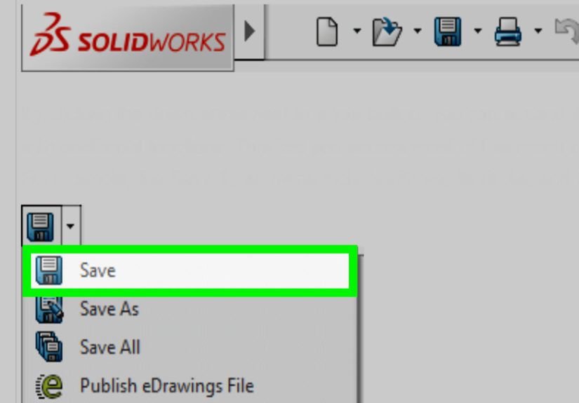
In SOLIDWORKS, go to File > Open, change the file type to AutoCAD files, then select the DXF or DWG. SOLIDWORKS will launch the DXF/DWG Import Wizard. This wizard matters. Do not speed-click through it like you are accepting cookie banners. It controls how the geometry enters your project.
You can usually choose from options such as creating a new SOLIDWORKS drawing, importing entities into a new part as a 2D sketch, or bringing in curves and model-related geometry. For drawings and title blocks, choose a drawing import. For a profile you want to extrude, import it as a sketch in a part.
Step 4: Map Layers and Check Units
Imported CAD files often carry layers from the original file. Some layers are useful. Others are construction lines, hidden notes, old revisions, or mysterious “Layer 0” leftovers from a CAD civilization long forgotten. Use layer mapping to bring in only what you need.
Next, check the units. A PDF conversion may come in as inches, millimeters, points, or something that appears to have been invented by a tired printer driver in 2009. Use a known dimension from the drawing to verify scale. If a 100 mm part imports as 3.94 inches, that may be fine. If it imports as 100 feet, it is time to adjust units before your bracket becomes a bridge.
Method 2: Import the Converted File as a SOLIDWORKS Drawing
If your goal is to recreate or preserve a 2D technical drawing, import the DXF/DWG as a SOLIDWORKS drawing. This is useful for legacy drawings, title blocks, templates, fabrication prints, and reference documentation.
During import, choose the option to create a new drawing and convert the entities into SOLIDWORKS entities. This allows you to edit geometry and annotations more easily than if you were simply viewing a static file.
After import, inspect the drawing carefully. Check line weights, fonts, dimensions, center marks, hidden lines, sheet scale, border alignment, and title block position. PDF-to-CAD conversions may create broken text, segmented arcs, extra lines, duplicated geometry, or hatch patterns that arrive with the emotional energy of confetti.
Method 3: Import the Converted File as a Sketch for 3D Modeling
If you want to turn a PDF drawing into a SOLIDWORKS part, import the DXF/DWG as a sketch. This is common when working from a 2D profile, flat plate, gasket, bracket, logo, enclosure outline, or laser-cut part.
Once the geometry is in a part file, use SOLIDWORKS sketch tools to clean it up. Delete duplicate segments, close open contours, merge endpoints, add relations, and apply Smart Dimensions. Then use features such as Extruded Boss/Base, Extruded Cut, Revolve, Sweep, or Sheet Metal tools to build the model.
Do not expect imported geometry to behave like a carefully created native SOLIDWORKS sketch. It may have too many tiny segments, missing constraints, or microscopic gaps. Use Repair Sketch, Check Sketch for Feature, and manual trimming to make it usable.
Method 4: Use a Scanned PDF as a Sketch Picture
When your PDF is scanned, converting it directly into clean CAD geometry can be messy. A practical alternative is to export the PDF page as an image, such as PNG, JPG, or TIFF, then insert it into SOLIDWORKS as a Sketch Picture.
How to Use Sketch Picture
- Open a new part in SOLIDWORKS.
- Start a sketch on the plane you want to use.
- Go to Tools > Sketch Tools > Sketch Picture.
- Select the exported image from the PDF.
- Position, rotate, and scale the image.
- Trace over the drawing using lines, arcs, splines, circles, and dimensions.
This method is slower, but it gives you control. It is often better than accepting a messy automatic conversion and spending hours cleaning up thousands of tiny line fragments.
Scale the Image Before You Trace
Scaling is everything. Find a known dimension on the drawing, such as an overall length, hole spacing, or diameter. Use that known value to scale the sketch picture correctly. Once the image is properly sized, trace the important geometry and define it with dimensions and relations.
Manual tracing may sound old-fashioned, but it is often the most reliable method for low-quality scans. Plus, it forces you to rebuild the design intelligently instead of importing a spaghetti sketch and hoping the Extrude command feels generous.
Method 5: Use Autotrace for Simple Shapes and Logos
SOLIDWORKS includes an Autotrace add-in that can convert high-contrast images into sketch geometry. It works best with simple black-and-white graphics, logos, silhouettes, and clean outlines. It is not ideal for complex mechanical drawings filled with dimensions, notes, section lines, and tiny details.
To use it, enable Autotrace under Tools > Add-Ins, then insert a Sketch Picture. The Autotrace controls can help detect edges and create sketch entities. After tracing, you will still need to clean up the result, add dimensions, remove junk geometry, and make sure contours are closed.
Autotrace is helpful, but it is not a magic intern. It can save time on the right image and waste time on the wrong one. If the scan is dirty, low-resolution, skewed, or full of gray shadows, clean the image first in an image editor before bringing it into SOLIDWORKS.
Method 6: Use PDF-to-CAD Conversion Software
Dedicated PDF-to-CAD tools can convert PDF drawings into DXF or DWG files. Some can handle vector PDFs very well and may also provide OCR or raster-to-vector conversion for scanned files. This can be useful when you have many PDFs, multi-page drawing sets, architectural plans, or old manufacturing prints.
However, conversion quality depends heavily on the original PDF. A clean vector PDF may convert nicely. A scan of a scan that was faxed, printed, folded, photographed, and emotionally abandoned will not become a perfect CAD file just because you bought software with a shiny button.
After conversion, always open the output in a CAD viewer or AutoCAD-style editor first if possible. Remove extra borders, notes, hatches, and title block clutter before importing into SOLIDWORKS. The cleaner the DXF/DWG, the cleaner your SOLIDWORKS sketch will be.
Common Problems When Converting PDF to SOLIDWORKS
Problem 1: The Scale Is Wrong
This is the classic issue. The geometry imports too large, too small, or slightly off. Always verify using a known dimension. If necessary, scale the sketch entities in SOLIDWORKS or fix units in the conversion software before importing again.
Problem 2: Arcs Become Tiny Line Segments
Some PDF conversions approximate curves with many small segments. This makes sketches heavy and hard to edit. Replace segmented curves with proper arcs, circles, or splines where possible. Your feature tree will thank you by not lagging every time you blink.
Problem 3: Text Imports Poorly
Fonts are tricky. TrueType text may import as editable text in some workflows, while SHX-style text may become geometry. If text is not important for modeling, delete it before importing. If it is important for a drawing, expect some cleanup.
Problem 4: The Sketch Will Not Extrude
Usually, this means the contour is not closed, there are overlapping entities, or tiny gaps exist between endpoints. Use sketch repair tools, zoom in on corners, and simplify the imported geometry. For complex profiles, it may be faster to trace a clean sketch over the imported one.
Problem 5: The File Is Too Heavy
Imported PDFs can create thousands of entities. Delete unnecessary geometry before importing, turn off irrelevant layers, simplify curves, and avoid importing full drawing sheets when you only need one profile.
Best Practices for a Clean PDF to SOLIDWORKS Conversion
- Start with the best PDF available. A native CAD-exported PDF beats a scanned copy every time.
- Convert to DXF or DWG first. SOLIDWORKS handles these formats much better than PDF.
- Import only what you need. Extra notes, hatches, borders, and title blocks can slow you down.
- Verify scale immediately. Do not model for two hours before discovering your part is 25.4 times too large.
- Clean geometry before feature creation. Close gaps, remove duplicates, and rebuild critical curves.
- Add dimensions and relations. Imported sketches are usually underdefined and need design intent.
- Use the PDF as a reference, not gospel. Old drawings may contain errors, missing tolerances, or outdated revisions.
Example: Converting a PDF Bracket Drawing Into a SOLIDWORKS Part
Imagine you have a PDF drawing of a flat steel bracket. It includes an outside profile, two mounting holes, a bend line, and a few dimensions. First, check whether the PDF is vector. If yes, convert it to DXF. Open the DXF in SOLIDWORKS and import it as a 2D sketch in a new part.
Next, delete the title block, dimensions, notes, and centerline clutter, leaving only the bracket profile and holes. Check the scale using the overall length from the drawing. If the bracket should be 150 mm long, measure the imported geometry. If it is wrong, scale it.
Then repair the sketch. Replace rough arcs with clean circles, make sure the outer contour is closed, and dimension the holes from useful datums. Once the sketch is clean, extrude it to the correct thickness. If the bracket includes bends, use sheet metal tools and rebuild the part with proper bend radius, thickness, and bend allowance rather than blindly extruding a flat outline.
Finally, create a SOLIDWORKS drawing from the new part and compare it against the original PDF. Check hole spacing, overall size, material thickness, and any notes. The result is not merely a converted PDF; it is a usable CAD model.
When You Should Remodel Instead of Convert
Sometimes the smartest conversion is no conversion. If the PDF is low quality, dimensioned clearly, and simple enough to understand, remodel the part from scratch in SOLIDWORKS. Manual remodeling gives you clean features, editable dimensions, and real design intent.
This is especially true for parts that need manufacturing updates, tolerance changes, simulation, CAM programming, or future revisions. A messy imported sketch might get you a quick visual result, but a native model will save time later. In CAD, “fast today” can become “why is this broken?” tomorrow.
Experience Notes: What Actually Works in Real PDF-to-SOLIDWORKS Projects
In real projects, the first lesson is simple: do not trust the PDF until it proves itself. A drawing may look precise on screen, but after conversion, small errors appear everywhere. Lines that look connected may have tiny gaps. Circles may become 96 little chords pretending to be a circle. Dimensions may not match the geometry. The title block may say “Scale 1:1,” but the imported file may arrive at a scale that suggests the printer had other dreams.
The most reliable habit is to identify one or two known dimensions before doing anything else. For mechanical parts, use hole center distance, overall length, or a known diameter. For architectural or layout drawings, use a grid spacing, door width, or dimensioned wall length. After import, measure that feature immediately. If it is wrong, fix scale before cleaning geometry. Scaling after you have added relations, dimensions, and features can create unnecessary headaches.
Another practical lesson: imported geometry should usually be treated as reference geometry, not finished geometry. Even when a PDF-to-DXF conversion looks good, it may not be ideal for parametric modeling. For example, a converted profile might contain hundreds of separate sketch entities where a native SOLIDWORKS sketch would use ten. That can make rebuilds slower and edits painful. A cleaner workflow is to place the imported geometry on a reference sketch, then create a new sketch over it using proper lines, arcs, circles, relations, and Smart Dimensions.
For scanned drawings, image preparation makes a huge difference. Before inserting a scan as a Sketch Picture, crop the page, increase contrast, straighten rotation, and remove shadows or stains if possible. A crisp black-and-white image is much easier to trace than a gray, fuzzy scan. If the drawing is skewed by even a degree or two, tracing becomes annoying because horizontal and vertical features will not line up with the SOLIDWORKS axes. Straighten first; model second.
Autotrace is useful, but only in the right lane. It can help with logos, decals, simple outlines, and organic shapes where exact engineering dimensions are less critical. For precision parts, manual sketching is usually better. The goal is not to capture every pixel; the goal is to rebuild the design accurately. A hole should be a real circle with a defined diameter, not a jagged loop made from tiny imported segments.
Layer cleanup is another time-saver. If you convert a full drawing sheet to DWG, open it first in a DWG editor and remove unnecessary layers before going into SOLIDWORKS. Delete dimensions, borders, revision clouds, hatches, notes, and hidden construction layers unless you truly need them. SOLIDWORKS performs much better when you import the useful profile rather than the entire historical biography of the drawing.
Finally, keep expectations realistic. PDF conversion is a bridge, not a teleportation device. It helps you move visible drawing information into a CAD workflow, but it does not recreate manufacturing intent automatically. Always verify critical dimensions, tolerances, and geometry against the original drawing. When the part matters, especially for machining, sheet metal, injection molding, or assemblies, rebuild the model carefully and use the PDF as a guide. That approach takes a little more discipline, but it creates SOLIDWORKS files that are easier to edit, easier to manufacture, and much less likely to make future-you mutter at the monitor.
Conclusion
Converting a PDF file to SOLIDWORKS is less about pressing one perfect button and more about choosing the right path. For vector PDFs, convert to DXF or DWG, then use the SOLIDWORKS DXF/DWG Import Wizard to bring the geometry in as a drawing or sketch. For scanned PDFs, use Sketch Picture, Autotrace, or dedicated raster-to-vector tools, then rebuild the important geometry cleanly.
The best results come from clean source files, careful scaling, selective importing, and a willingness to remodel critical features instead of trusting messy converted geometry. Once you understand the workflow, a PDF stops being a dead-end document and becomes a useful starting point for drawings, sketches, reverse engineering, and 3D design.